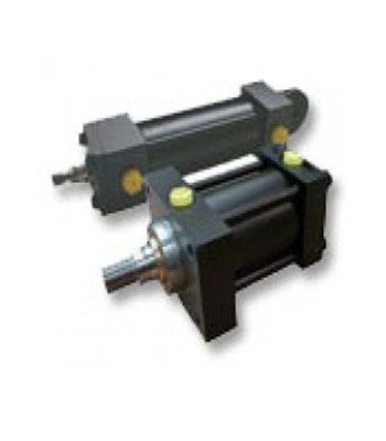
Parker Hydraulic Cylinder
0,00 €| Model : | – |
| Description : | PARKER Hydraulic Cylinder, Powerful, Very accurate and fast, professional and High strength, high quality, the ability to work in extreme conditions, ideal for complex tasks, High pressure, these Cylinders in sizes offered these cylinders are offered in different sizes |
Company name : | Padideh Hydraulic & Pneumatic |
| Packaging : | Box |
Minimum order : | 1 |
| Standard : | – |
Production power : | 100 |
| Payment type : | Cash |
Source : | www.hydpne.com |
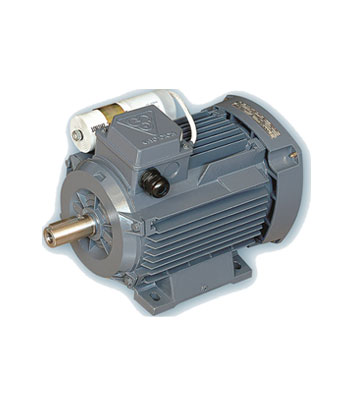
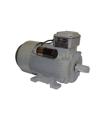
Phase Capacitor Run Electro Motors
0,00 €Dimension (Foot mounting – Flange mounting)
| Frame No.IEC | T | S | P | N | M | LA | AK | HD | H | C | B | BA | K | KB | AB | A | AA | HA | AC | Z | Q | I | L | E | EH | DH | GA | LK | F | D | FLANGE SYS.IEC 72-1 |
|---|---|---|---|---|---|---|---|---|---|---|---|---|---|---|---|---|---|---|---|---|---|---|---|---|---|---|---|---|---|---|---|
| 56 | 3 | 7 | 120 | 80 | 100 | 8 | 105 | 145 | 56 | 36 | 71 | 19 | 6 | 10 | 112 | 90 | 22 | 10 | 106 | 76 | 55.5 | – | 189 | 20 | – | – | 10.2 | 12 | 3 | 9 | FF100 |
| 63 | 3 | 10 | 140 | 95 | 115 | 10 | 106 | 158 | 63 | 40 | 80 | 25 | 7 | 10 | 125 | 100 | 25 | 10 | 123 | 76 | 54.5 | – | 214 | 23 | – | – | 12.5 | 12 | 4 | 11 | FF115 |
| 71 | 3.5 | 10 | 160 | 110 | 130 | 10 | 110 | 175 | 71 | 45 | 90 | 18 | 7 | 10 | 140 | 112 | 28 | 11 | 138 | 76 | 58 | – | 241 | 30 | – | – | 16 | 18 | 5 | 14 | FF130 |
| 80 | 3.5 | 12 | 200 | 130 | 165 | 12 | 130 | 194 | 80 | 50 | 100 | 25 | 10 | 14 | 160 | 125 | 35 | 11 | 156 | 96 | 68.5 | – | 276 | 40 | – | – | 21.5 | 25 | 6 | 19 | FF165 |
| 90L | 3.5 | 12 | 200 | 130 | 165 | 12 | 137 | 215 | 90 | 56 | 125 | 30 | 10 | 14 | 182 | 140 | 43.3 | 12 | 175 | 96 | 70.5 | – | 325 | 50 | 19 | M8 | 27 | 32 | 8 | 24 | FF165 |
| 100L | 4 | 15 | 250 | 180 | 215 | 12 | 145 | 233 | 100 | 63 | 140 | 35 | 12 | 17 | 200 | 160 | 40 | 12 | 194 | 96 | 73.5 | – | 366 | 60 | 22 | M10 | 31 | 40 | 8 | 28 | FF215 |
| 112M | 4 | 15 | 250 | 180 | 215 | 12 | 155 | 256 | 112 | 70 | 140 | 35 | 12 | 17 | 235 | 190 | 45 | 13 | 217 | 96 | 76.5 | 200 | 384 | 60 | 22 | M10 | 31 | 40 | 8 | 28 | FF215 |


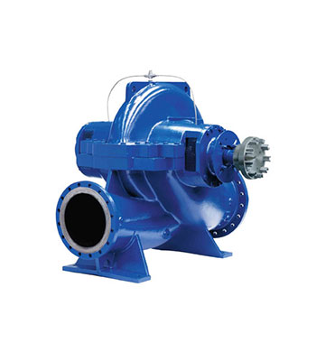
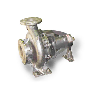
Pump type BB1– According to API 610
0,00 €Design:
- Horizontal, axially split, one-and two stage between bearings
- Double suction impeller
- Single or double volute, depending on size
- Diffuser or overflow piece after first stage for two stage execution
- Driving from both sides possible
- Mechanical seals (single, double, tandem)
- Oil lubricated rolling bearings with rotor located by the non drive end for residual hydraulic axial thrust from hydraulically balanced impeller
- Radial as well as axial loads can be also taken by oil lubricated bearings
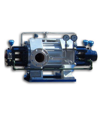
Pump type OH1-According to API 610
0,00 €Usages:
- Oil and Gas
- Petrochemical
- Power Plant
Product features
Design:
- Single-casing, radially split between bearings
- Segmental ring section pumps with tie-rods
- Single suction Impeller
- Sealing between segments by O-rings
- Mechanical shaft seal with single, double or tandem seal
- No limitation for pressures, Spec. gravity and dimensions of casing
- Axial bearing necessary additionally to balancing device
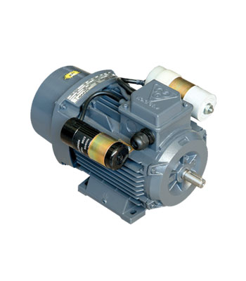
Single Phase Double Capacitor Electro Motors
0,00 €Dimension (Foot mounting – Flange mounting)
| Frame No.IEC | T | S | P | N | M | LA | AK | HD | H | C | B | BA | K | KB | AB | A | AA | HA | AC | Z | Q | L | E | EH | DH | GA | LK | F | D | FLANGE SYS.IEC 72-1 |
|---|---|---|---|---|---|---|---|---|---|---|---|---|---|---|---|---|---|---|---|---|---|---|---|---|---|---|---|---|---|---|
| 56 | 3 | 7 | 120 | 80 | 100 | 8 | 210 | 145 | 56 | 36 | 71 | 19 | 6 | 10 | 112 | 90 | 22 | 10 | 106 | 76 | 55.5 | – | 20 | – | – | 10.2 | 12 | 3 | 9 | FF100 |
| 63 | 3 | 10 | 140 | 95 | 115 | 10 | 212 | 158 | 63 | 40 | 80 | 25 | 7 | 10 | 125 | 100 | 25 | 10 | 123 | 76 | 54.5 | – | – | -23 | – | 12.5 | 12 | 4 | 11 | FF115 |
| 71 | 3.5 | 10 | 160 | 110 | 130 | 10 | 220 | 175 | 71 | 45 | 90 | 18 | 7 | 10 | 140 | 112 | 28 | 11 | 138 | 76 | 58 | 283 | 30 | – | – | 16 | 18 | 5 | 14 | FF130 |
| 80 | 3.5 | 12 | 200 | 130 | 165 | 12 | 260 | 194 | 80 | 50 | 100 | 25 | 10 | 14 | 160 | 125 | 35 | 11 | 156 | 96 | 68.5 | 331 | 40 | – | – | 21.5 | 25 | 6 | 19 | FF165 |
| 90L | 3.5 | 12 | 200 | 130 | 165 | 12 | 274 | 215 | 90 | 56 | 125 | 30 | 10 | 14 | 182 | 140 | 43.3 | 12 | 175 | 96 | 70.5 | 380 | 50 | 19 | M8 | 27 | 32 | 8 | 24 | FF165 |
| 100L | 4 | 15 | 250 | 180 | 215 | 12 | 290 | 233 | 100 | 63 | 140 | 35 | 12 | 17 | 200 | 160 | 40 | 12 | 194 | 96 | 73.5 | 428 | 60 | 22 | M10 | 31 | 40 | 8 | 28 | FF215 |
| 112M | 4 | 15 | 250 | 180 | 215 | 12 | 300 | 256 | 112 | 70 | 140 | 35 | 12 | 17 | 235 | 190 | 45 | 13 | 217 | 96 | 76.5 | 440 | 60 | 22 | M10 | 31 | 40 | 8 | 28 | FF215 |
Single-Phase Double-Capacitor Electro Motors With Cast-Iron Frame
0,00 €Product Specification
| Type | Frame size | Output Power | Output Power | Rated Voltage | Speed in rated load | Rated Current | Rated Torque | Efficiency (%) | Power factor | Starting / Rated Current | Starting / Rated Torque | Break down / Rated Torque | Inertia moment | Capacitor Run | Capacitor Run | Capacitor Start | Capacitor Start | Poles |
|---|---|---|---|---|---|---|---|---|---|---|---|---|---|---|---|---|---|---|
| CRS 100L4B | 100L | 2.2 | 3 | 220 | 1440 | 13.5 | 14.59 | 78 | 0.95 | 4.6 | 1.9 | 1.9 | 0.004613 | 60 | 400 | 230 | 330 | 1 |


